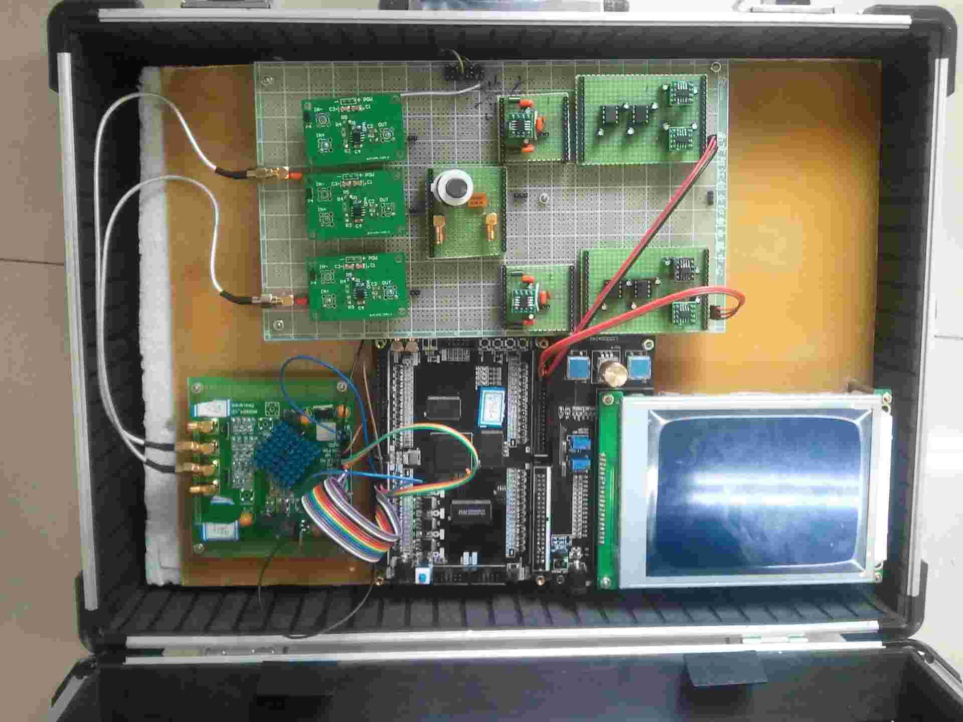
This blog presents a cost-effective and efficient solution for measuring frequency characteristics of a given network. Developed as part of the National Undergraduate Electronic Design Contest in 2013, this analyzer was designed for practical applications, emphasizing user interaction experience, simplicity and reliability.
System Design
The system integrates the following key components:
- A signal generator to produce the required test signals.
- An analog-to-digital conversion module for precise data acquisition.
- Microcontroller-based processing for real-time analysis and data handling.
- A user-friendly interface for displaying results.
Signal Generator Design: The signal generator is a core part of the system, capable of generating signals in various waveforms (sine, square, etc.) and frequencies. It leverages FPGA to generate digital signals and utilizes a digital-to-analog conversion module and an operational amplifier to ensure consistent output quality.
Analog-to-Digital Conversion Module: The module is built using a high-precision ADC chip, ensuring minimal signal distortion during the digitization process. This enables accurate frequency response measurements even for high-frequency signals.
Microcontroller and Processing: The microcontroller is responsible for controlling the frequency sweep, processing the digitized signal, and analyzing the amplitude and phase response.
Hardware Implementation
The hardware design prioritizes compactness and ease of assembly. The signal generator is capable of producing sinusoidal signals with adjustable frequency and amplitude. This flexibility allows testing across a wide frequency range. The system uses a LCD touchscreen to display the measurement results and enables users to interact with the system smoothly.


